Monitoring Data Cannot Hold an Excavation: Pre-Agree the Action Plan
A decision-led monitoring plan for Iranian deep excavations that turns movement, groundwater and site observations into timely, accountable action.
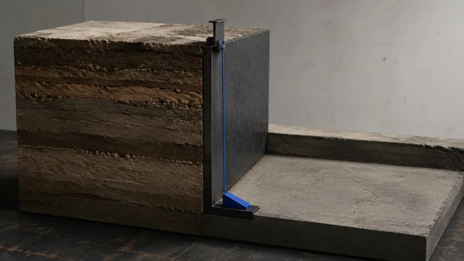
A reading is not control until it changes a decision
ISO 18674-1 defines geotechnical monitoring as a complete project that includes planning, risk assessment, specification, procurement, installation, data collection, processing, evaluation and reporting. FHWA guidance likewise says instruments should answer specific critical questions and that findings should reach the design team promptly with geotechnical interpretation. A graph delivered after the next excavation stage therefore may be valid data but failed control. [1][6]
The practical position for a deep excavation in Iran is simple: do not buy a sensor package before defining the decisions it must protect. The monitoring plan should say which observation can permit the next dig, require a check, change the sequence, add support, reduce dewatering, protect an adjacent asset, stop work or allow restart. If nobody has the authority and time to make that decision, continuous data only produces a faster archive of unmanaged risk.
Start with consequences, receptors and credible mechanisms
Hong Kong GEO's 2024 guidance starts trigger design from the tolerable serviceability and safety limits of affected receivers and calls for early consultation with owners, maintainers and utility operators. CIRIA C760 connects retaining-wall type, construction sequence and the Observational Method rather than treating monitoring as an accessory to a finished design. These are transferable principles; their local empirical movement values are not universal limits for another country or ground condition. [5][8]
Build one risk-to-decision register before the instrumentation schedule. For each excavation stage, name the credible mechanism, the exposed people or asset, the earliest observable change, the independent confirmation, the design assumption being checked and the response time available. In an Iranian urban project, the review may need to test undocumented foundations, vulnerable boundary walls, buried utilities, groundwater drawdown, variable fill, nearby traffic or construction, access to neighbouring property, and the reliability of power, communications and calibration support. These are questions to investigate, not assumed facts about every site.
- Decision: what exactly will be released, held, modified or stopped?
- Receiver: which person, structure, service, road, excavation support or water-sensitive ground is protected?
- Mechanism: wall deflection, ground loss, settlement, heave, piping, basal instability, anchor or strut load, vibration, or distress?
- Time: can the measurement, verification, escalation and physical response finish before the next harmful change?
Design an observation network, not an instrument shopping list
The ISO 18674 series separates general system rules from method-specific measurement. Part 3 covers displacement across a line by inclinometers, while Part 4 covers pore-water pressure and piezometric level. The current ISO/DIS 18674-9—explicitly a draft under development—extends the framework toward geodetic displacement measurements and also discusses techniques such as InSAR, terrestrial radar, laser scanning and GNSS in informative annexes. More technology does not remove the need to choose a parameter that reveals the mechanism in time. [1][2][3][4]
Match each question to at least one direct observation and, for high-consequence decisions, an independent or differently vulnerable check. A wall inclinometer can describe deformation along its casing but not by itself prove the condition of an adjacent brittle pipe. A settlement point can move because its control moved. A piezometer can be responsive, clogged, poorly sealed or located outside the critical water regime. Draw the zone of influence, predicted deformation shape, groundwater boundaries, support stages and receiver locations together; then place instruments where competing explanations can be distinguished.
- State the parameter, expected range, required resolution, uncertainty and direction of measurement.
- Show the instrument, reference control and critical depth or elevation on the design section—not only on a plan.
- Define manual observations for cracks, seepage, ground loss, support damage, unusual noise and construction departures.
- Protect cables, prisms, casings, benchmarks and access routes from the work they are intended to monitor.
Commission the baseline and the whole measurement chain
ISO 18674-1 distinguishes initial, zero, baseline and reference measurements, and treats commissioning as demonstration and acceptance of the installed monitoring system. FHWA asks for timing that captures seasonal or expected variation, standardized collection and recordkeeping, and timely communication. A first reading taken after dewatering, guide-wall work, anchor stressing or excavation has begun is not a neutral history; it must be labelled against what had already changed. [1][6]
Commission from the physical sensor to the decision recipient. Confirm identity, location, orientation, datum, units, calibration, installation record, readout or logger configuration, time zone, conversion formula, plausibility checks, transmission, dashboard transformation, notification and acknowledgement. Run a witnessed test in which a known input or simulated alarm reaches the named duty holder. Where a perfect end-to-end physical test is impossible, document which links were tested separately and what uncertainty remains.
- Obtain a stable pre-work baseline long enough to understand noise and relevant natural variation.
- Record every re-zero, damaged point, replaced probe, changed coordinate control and missed reading without erasing history.
- Test a manual reading and an independent survey against the automated route where consequences justify redundancy.
- Do not release the monitored stage until baseline quality, alarm routing and response availability are accepted.
Attach every trigger to a pre-agreed action and authority
GEO TGN 54 uses five escalating levels, each with explicit response actions, and stresses that affected stakeholders should be consulted on monitoring locations, tolerable limits and responses. It also treats sudden change, significant groundwater seepage, visible ground loss and distress as special conditions rather than relying only on cumulative displacement. The lesson is the architecture of escalation—not the document's Hong Kong-specific numbers. [5]
Set project-specific levels from the design predictions, uncertainty, receiver tolerance, measurement uncertainty and time needed to respond. Use both magnitude and rate where the mechanism demands it. The matrix should state who validates an apparent exceedance, which work may continue, who is notified, the maximum response time, the physical contingency, the evidence required to resume and who has final authority. A commercial manager must not be left to invent the engineering response at 02:00, and an automated alert must not independently authorize a structural intervention.
- Observe: increase frequency, inspect the work and receiver, and confirm the trend against construction events.
- Review: hold the affected stage, verify the reading independently, review the ground model and mobilize the designer.
- Act: stop defined activities, make the area safe, execute the engineered contingency and notify named stakeholders.
- Restart: require documented cause review, stabilization evidence, revised method where needed, and signed authorization.
Keep an offline response route and an authoritative record
USACE's 2025 ER 1110-1-8178 requires performance-monitoring data to be stored in an authoritative database, geospatially referenced with datums, coordinate systems and metadata, and validated through documented QC/QA. It also explains why unmanaged duplicates create conflicting records and why construction monitoring data may matter through operation and maintenance. That policy applies to USACE, not Iran, but its information-control logic is useful for any owner who may later need to reconstruct what moved, when and under which work stage. [7]
Specify one controlled record that preserves raw readings, processed values, algorithms or formulas, instrument and location IDs, construction events, weather or pumping context where relevant, alerts, acknowledgements, decisions, inspections, photographs and superseded records. Provide a phone-and-paper escalation route when site connectivity, power or cloud access fails. Export an open, readable handover package rather than leaving the only history inside a vendor account, and assign retention and access according to the contract and governing requirements.
- One timestamp convention and time zone across logger, site diary, survey, alert and decision records.
- One owner for data validation and one accountable engineer for interpretation; neither role is an unattended algorithm.
- A visible status for missing, late, suspect, replaced or unreviewed data so absence cannot look like stability.
- A tested offline call tree with current names, deputies, acknowledgement times and a controlled paper trigger matrix.
Pilot one excavation stage and measure decision performance
Before the first high-consequence stage, run a tabletop exercise and a live commissioning drill. Simulate one plausible trend, one sudden special condition, one failed instrument and one communications outage. Ask the surveyor, instrumentation provider, site manager, temporary-works or excavation-support designer, geotechnical engineer, safety lead, owner representative and affected asset contact to act from the same controlled matrix. Close unclear authority, unavailable contingency materials and notification gaps before deeper excavation exposes them.
Measure the control system, not the number of installed sensors: percentage of critical instruments commissioned before the relevant work; baseline completeness; valid readings received on time; median time from reading to validation, engineering interpretation, acknowledgement and site action; false or unexplained alarm rate; time with critical coverage unavailable; overdue inspections; trigger events with a complete decision record; and restart approvals supported by stabilization evidence. Always show the denominator and review trends by excavation stage.
The governing point is restraint: monitoring cannot compensate for an inadequate excavation-support design, unsafe sequence, uncontrolled dewatering, poor installation or missing supervision. Foreign examples do not supply Iranian trigger values or permissions. Final design, instruments, limits, frequency, access, protection of neighbours and utilities, emergency measures, stop-work and restart decisions must follow applicable Iranian requirements, the signed contract, project-specific ground and groundwater evidence, actual construction, and responsible geotechnical, structural, temporary-works and safety review.
Sources & further reading
These primary sources support the claims and implementation frameworks used in this field note.
- 1. ISO 18674-1:2015 — Geotechnical monitoring by field instrumentation: General rules
International Organization for Standardization
- 2. ISO 18674-3:2017 — Measurement of displacements across a line: Inclinometers
International Organization for Standardization
- 3. ISO 18674-4:2020 — Measurement of pore water pressure: Piezometers
International Organization for Standardization
- 4. ISO/DIS 18674-9 — Measurement of displacements by geodetic means (draft under development)
International Organization for Standardization
- 5. GEO Technical Guidance Note No. 54 — Guidelines on Ground Deformation Control Mechanism for Geotechnical Works
Geotechnical Engineering Office, Hong Kong Civil Engineering and Development Department
- 6. Project Development and Design Manual, Chapter 6 — Geotechnical
U.S. Federal Highway Administration
- 7. ER 1110-1-8178 — Data Management for Subsurface Investigations and Performance Monitoring Instrumentation
U.S. Army Corps of Engineers
- 8. C760 — Guidance on embedded retaining wall design
Construction Industry Research and Information Association
Sources were checked on 3 September 2026. The foreign standards and guidance do not create Iranian legal obligations, design methods or trigger limits. Final limits, excavation sequence, monitoring, stop-work and restart decisions must follow governing requirements, the signed contract, the project ground and groundwater model, the condition of adjacent assets, actual site conditions, and responsible professional review.