Firestop Sealant Has No Rating: Build a Penetration Evidence Gate
A practical control plan for Iranian projects that matches every service penetration to an assessed system, inspects it before concealment, and preserves the record for future change.
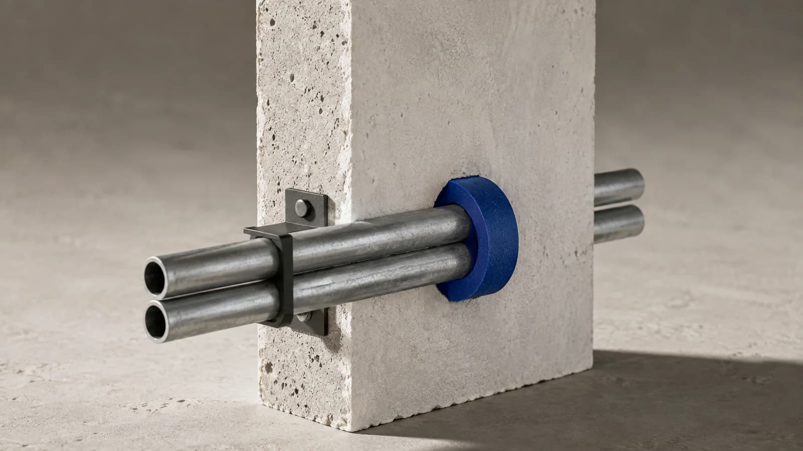
A cartridge is not a fire-rated system
ISO 10295-1:2026 evaluates whether a penetration sealing system maintains the integrity and insulation of the fire-separating element at the penetration. ASTM E814-26 likewise makes performance depend on the specific tested assembly: the wall or floor, opening, number, type and size of services, and firestop materials. UL's guide is explicit that ratings apply to complete systems, not interchangeable components. [1][2][6]
OlbrichCo's position is therefore strict: do not approve firestop by product name, colour or a photograph of sealant. Approve the installed condition against a documented evidence basis. If the actual wall, service, annular space, backing, depth, support or movement condition sits outside that basis, the penetration remains unresolved even when the finish looks neat.
- Define the fire barrier and required performance before any trade forms an opening.
- Treat each penetration as an assembly with interfaces, not as a consumable-material purchase.
- Keep smoke, air, water, acoustic and fire claims separate unless the evidence addresses each one.
- Let governing requirements, the fire strategy and responsible review set the required rating.
Schedule the barrier before the opening
ASTM E814 distinguishes flame-based F ratings from T ratings that also address temperature rise, while warning that the test does not reproduce every real-fire force, such as falling debris or failed cable supports. UL separates through-penetrations, membrane penetrations, joints and perimeter barriers because they are different applications with different evidence. One generic detail cannot safely cover all four. [2][6]
Create a penetration schedule from the compartment drawings before coordinated openings are released. For every planned breach, record a stable ID, barrier location and construction, required performance, service material and outside dimensions, insulation, opening geometry, annular space, sleeve, backing, seal depth, service supports, movement demand, access side, selected evidence reference and responsible parties. Reserve entries for later services; do not let unplanned holes bypass the schedule.
- Overlay architectural fire barriers with structural and MEP openings at a formal coordination gate.
- Assign who designs the opening, supports the service, installs the system, inspects it and closes the ceiling or shaft.
- Flag mixed services, plastic pipes, insulated pipes, cable trays, combustible sleeves and inaccessible faces for early review.
- Give site teams a controlled offline detail pack where dependable connectivity cannot be assumed.
Match the real condition—and stop at substitution
UL's guide says the components specified in a certified system are not intended to be interchanged unless the individual system or applicable guidance permits it. ASTM E2750-23 addresses qualified extension of test data, but limits extrapolation and warns that multiple changes may have a different cumulative effect from one evaluated change. A casual site substitution is not an engineering assessment. [4][6]
At submittal, compare the proposed condition line by line with the evidence: supporting construction, orientation, rating, service type and material, dimensions, bundle or cable fill, opening and annular limits, sleeve, backing, sealant depth, collars or wraps, supports and movement. Classify the outcome as exact match, permitted variation, justified project-specific assessment, or redesign. Freeze procurement only after the route and approval authority are clear.
- Reject the phrase ‘or equivalent’ unless equivalence is defined against the complete system.
- Record batch and shelf-life data without implying that traceability alone proves performance.
- Route every changed pipe, insulation, wall build-up or opening size back through technical review.
- Keep superseded details available but visibly withdrawn so site teams cannot reuse them.
Mock up the hardest interface, not the easiest hole
ASTM E3157-25 covers substrate preparation, installation procedures, material functions and environmental conditions that can affect installation. It also notes that opening location, dimensions and creation method are critical even though they sit outside that guide's design scope. UL similarly directs installation to the published system and manufacturer instructions. The evidence chain starts before the sealant is opened. [5][6]
Build a witnessed first-work sample around the highest-risk recurring condition: crowded cable tray, insulated pipe, uneven masonry, thin partition, shaft edge or a location with limited access. Confirm opening quality, service spacing and support, sequence, cleaning, backing, depth control, wet-film or cure requirements where applicable, identification and inspectability. Use the accepted sample to train crews and expose coordination failures before repetition makes repair expensive.
- Hold incompatible products, wet or contaminated substrates, damaged packaging and expired material outside the workface.
- Prove how the installer will measure hidden backing and seal depth rather than judging only the surface.
- Coordinate access so inspection can occur on every required face before cladding, ceilings or shaft walls close.
- Repeat the sample when a material, crew, substrate or critical geometry changes.
Make concealment a signed hold point
ASTM E2174-24 establishes procedures for field verification and inspection of installed firestop systems against inspection documents by qualified inspectors; it does not select products or create performance criteria. UL's application guide links inspection to the listed system or justified assessment and identifies contractor documentation, material verification, scheduling, inspection and reporting as parts of the process. [3][6]
Inspect while the assembly is visible and measurable. Verify the ID, barrier and service against the approved detail; check opening size, annular space, backing, depth, accessories, service support, adhesion, damage and required faces; then record status, inspector, date and defect disposition. Photographs should include context and a scale, but a photo alone cannot establish concealed depth or evidence compatibility. No closure release should rely on an unresolved punch list.
- Use a clear result: accepted, rejected, or held for technical resolution—never merely ‘photographed’.
- Separate installer self-checks from independent or contractual inspection where the project requires it.
- Reinspect repaired work and preserve both the original defect and the verified closure.
- Sample only where the approved inspection plan allows it; consequence and repetition should drive intensity.
Handover a maintainable barrier, not a photo folder
UK Building Safety Regulator guidance treats compartmentation as something that must be designed, built and maintained, and specifically warns that later service work or refurbishment can damage firestopping. It calls for records of original design and construction, current condition and subsequent changes. That operating principle is useful beyond its UK legal scope: every future cable can reopen today's accepted barrier. [7]
Deliver a searchable penetration register linked to floor, zone and barrier drawings, with approved evidence, installed configuration, product and batch records, inspection, defects, repairs and closure authorization. A physical label or QR code may speed retrieval, but keep a human-readable identifier and offline export. Give facility teams a permit-to-penetrate workflow: identify the barrier, review the proposed change, protect the opening temporarily, reinstate an approved system and update the authoritative record.
- Reconcile the register against the building before handover; model completeness is not field completeness.
- Define who owns inspections after tenant fit-out, maintenance, telecom work and equipment replacement.
- Preserve access to evidence beyond a vendor subscription or the construction team's accounts.
- Escalate damaged, unknown or inaccessible systems according to the fire strategy and responsible review.
Pilot one riser and measure control, not sealant volume
Choose one consequential riser, plant-room boundary or repeated corridor wall. Baseline planned openings, unplanned openings, first-pass inspection, defect closure time and missing evidence. Run the full cycle from coordinated schedule and technical match through witnessed installation, concealment release and record retrieval. Include one controlled service change so the operating workflow is tested before occupancy.
Track schedule coverage, exact-match rate, undocumented substitutions, percentage inspected before concealment, first-pass acceptance, median defect-closure time, reopened penetrations and time to retrieve an accepted record. These indicators measure control quality, not fire performance or legal compliance. Scale only after the team can explain every exception and the responsible professionals accept the project-specific method under governing Iranian requirements and actual site conditions.
- Target zero concealed penetrations without an accepted ID and evidence route.
- Review recurring defects by interface and trade instead of hiding them in one project-wide percentage.
- Audit a sample from drawing to physical opening and back from site label to approved evidence.
- Revisit the plan when the fire strategy, barrier build-up, service package, supply or operating use changes.
Sources & further reading
These primary sources support the claims and implementation frameworks used in this field note.
- 1. ISO 10295-1:2026 — Fire tests for building elements and components: Penetration seals
International Organization for Standardization
- 2. ASTM E814-26 — Standard Test Method for Fire Tests of Penetration Firestop Systems
ASTM International
- 3. ASTM E2174-24 — Standard Practice for On-Site Inspection of Installed Firestop Systems
ASTM International
- 4. ASTM E2750-23 — Standard Guide for Extension of Data from Penetration Firestop System Tests
ASTM International
- 5. ASTM E3157-25 — Standard Guide for Understanding and Using Information Related to Installation of Firestop Systems
ASTM International
- 6. Firestop and Joint Application Guide
UL Solutions
- 7. Managing safety risks in high-rise residential buildings: A detailed guide
UK Building Safety Regulator
Sources were checked on 5 September 2026. ISO 10295-1:2026 and ASTM E814-26 describe international test practice; they do not create an Iranian legal obligation or rating. Final compartmentation, resistance period, test or assessment route, competence, inspection, repair and acceptance must follow governing requirements, the project fire strategy, the signed contract, the actual installed assembly, and responsible fire, architectural, structural and building-services review.