The Frame May Survive While the Building Fails: Restrain Nonstructural Systems
A practical owner-to-site plan for keeping ceilings, services, equipment, partitions, and critical contents safe and usable after earthquake shaking.
Structural survival is not the same as a usable building
FEMA P-2090/NIST SP 1254 separates three post-earthquake milestones: safe reoccupancy, functional recovery, and full recovery. Functional recovery goes beyond safe entry; it requires enough components and services to support a significant share of the building’s intended use. NIST SP 1321 translates that direction into design features that include cladding and partition deformation capacity, stair and elevator performance, pipe and duct bracing, equipment anchorage, and equipment prequalification. [1][2]
OlbrichCo’s operating view is that a frame-only seismic brief leaves the owner with an undefined business risk. A hospital wing without water, a data room without cooling, a factory without a secured electrical cabinet, or a residential tower with damaged ceilings may be structurally standing yet unavailable. The project must define what ‘usable’ means before the nonstructural packages are procured.
Set the recovery objective room by room and system by system
The NIST-FEMA framework defines a functional-recovery objective as restoration of basic intended functions within an acceptable time after a specified earthquake, with the time allowed varying by building use. It also makes clear that reoccupancy can precede functional recovery: a building may be safe to enter while important services remain unavailable. [1]
Do not convert this concept into one vague project label. For each critical space and service, state the required function, acceptable interruption, dependencies, safe degraded mode, inspection needed before restart, and party authorised to release it. An Iranian hotel, clinic, warehouse, data room, production line, or residential building will not share the same priorities; the owner must rank them rather than asking every component to meet an undefined premium standard.
- Function: what activity or safety service must continue or return first?
- Consequence: could failure injure people, block egress, release water or hazardous contents, or stop a critical operation?
- Dependency: which power, water, controls, communications, access, staff, and external utilities are required?
- Evidence: what inspection, test, record, spare, and named approval will permit restart?
Build a critical inventory, not a generic MEP note
ISO 13033 covers architectural elements, mechanical and electrical systems, and building contents supported by or attached to new or existing buildings. NIST SP 1321’s nonstructural design set spans cladding, partitions, stairs, elevators, domestic plumbing, fire suppression, HVAC, and electrical equipment. The boundary is therefore wider than rooftop machinery or large suspended pipework. [2][3]
FEMA E-74 provides survey, prioritisation, responsibility, specification, installation, and inspection tools for both existing and new buildings. Its examples also show that adjacent systems can damage each other when they move differently—for example, ceilings and sprinkler heads, or unbraced pipes sharing a congested zone. [4]
Create one register tied to locations and asset IDs. Include ceilings, partitions, façades, stone finishes, stairs, tanks, pumps, chillers, fans, ducts, pipes, cable trays, panels, batteries, racks, laboratory or process equipment, stored hazardous material, and contents whose movement could block an exit. Rank each item by life safety, functional consequence, replacement lead time, access for repair, and interaction with neighbours.
Trace the load path from the component into the real structure
ISO 13033 provides a basis for deriving seismic actions and verifying the capacity of nonstructural components and systems, while ASCE/SEI 7-22 is a loading standard that includes seismic design provisions. These are design frameworks, not universal values to paste into an Iranian submittal; the governing local requirements and project structural engineer must establish the applicable hazard, demand, deformation, importance, and acceptance route. [3][5]
For every critical item, draw the complete route: component body to base or hanger; restraint to connection; connection to anchor or insert; anchor into the verified concrete, masonry, or steel support; and support back into the primary structure. Check both force and imposed movement. A strong brace attached to a thin screed, an unknown blockwork leaf, an unverified insert, or a slab zone with reinforcement conflict is not a complete load path.
Coordinate operating vibration, thermal movement, building drift, seismic separation, maintenance removal, fire rating, waterproofing, and access. Where proprietary anchors or certified equipment may be substituted during procurement, approve the exact substrate, edge distance, embedment, installation tool, orientation, accessories, and evidence before the site commits to holes or cast-in inserts.
Separate equipment qualification from installation acceptance
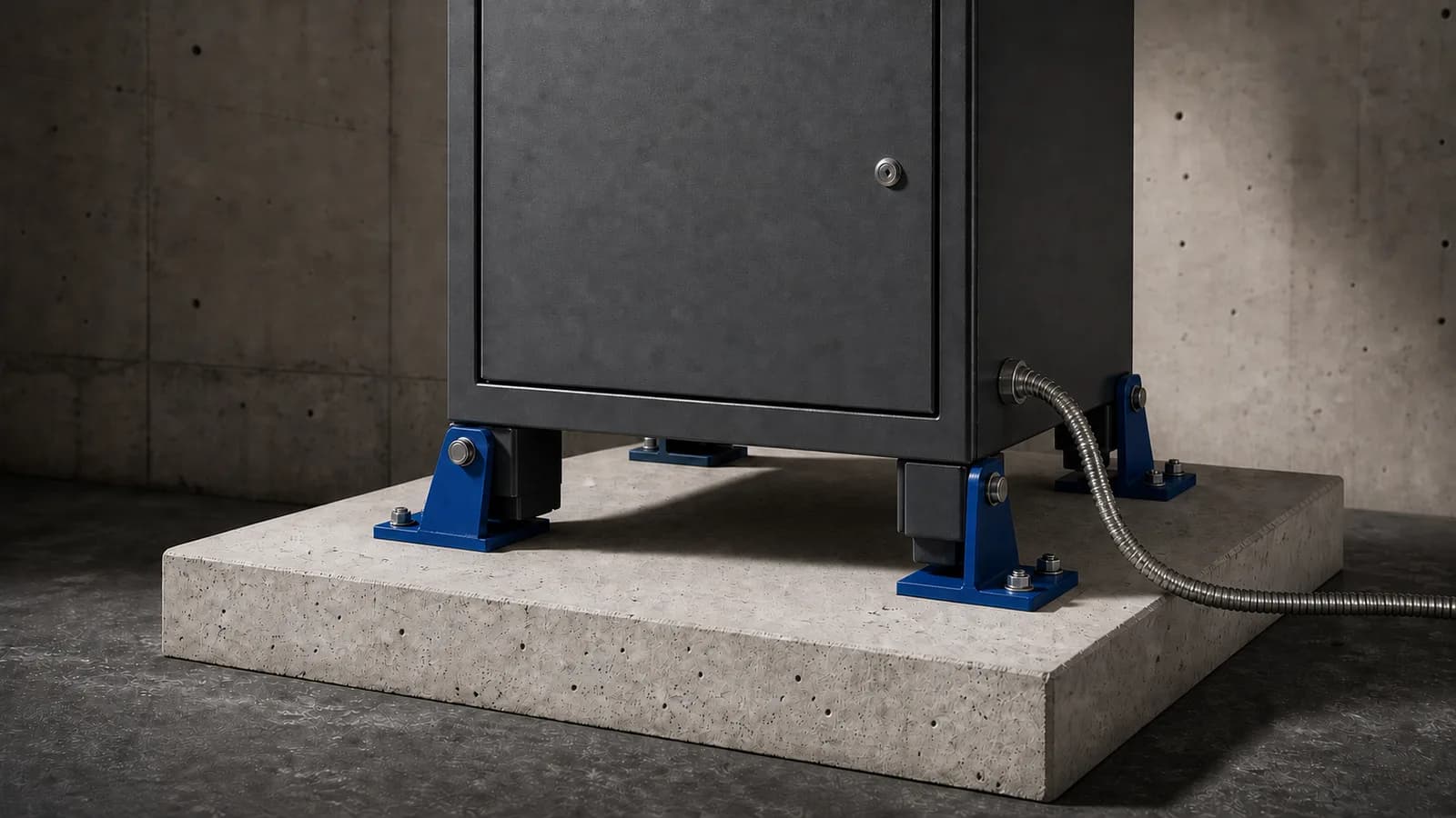
ICC-ES states that AC156 (24) 2nd Edition, published in April 2025, addresses seismic certification of nonstructural components by shake-table testing. NIST SP 1321 treats equipment prequalification and equipment anchorage as separate nonstructural design actions. A certificate for the cabinet or machine therefore does not, by itself, verify the project’s plinth, anchors, restraints, connections, or attached services. [2][6]
ASTM E580/E580M-24a illustrates the same system logic for suspended ceilings: it is an installation practice for suspension systems and related components, and it leaves applicability to the authority having jurisdiction. FEMA E-74 likewise assigns design, construction, observation, and inspection responsibilities rather than treating a product data sheet as completed work. [4][7]
Make the submittal cross-reference explicit: tested model and configuration; mounting position; supported weight and centre of gravity; internal components; test demand and acceptance criterion; required restraints; approved anchors and substrate; flexible service connections; and post-installation inspection. If any field condition falls outside the evidence, return it for engineering review rather than extending the certificate by assumption.
Control interfaces and field installation with hold points
FEMA E-74 identifies interaction as a damage mechanism when neighbouring nonstructural systems have different shapes, dynamic behaviour, or bracing needs. ASTM E580/E580M-24a similarly treats the ceiling as an installed system, not only a grid product. The practical implication is that ceiling, lighting, sprinkler, partition, duct, cable-tray, and equipment teams cannot close their work independently in a shared zone. [4][7]
Use coordinated zone drawings and inspection hold points before ceilings, shafts, risers, panels, and equipment bases become inaccessible. Verify the supporting substrate, approved anchor, drilling method and depth, cleaning, torque or setting record where applicable, brace angle and length, clearance, flexible connection, corrosion protection, fire stopping, and access. Photograph the installed condition with a location reference, but retain measured records and approvals; a photograph alone does not prove capacity.
- Design release: approved demand, movement, detail, substrate, responsibility, and submittal evidence.
- Pre-installation: actual support scanned or opened, conflicts cleared, installers briefed, and approved tools available.
- Pre-close: anchors, braces, clearances, services, labels, and inspection records checked in the real location.
- Handover: as-built location, deviations, certificates, photographs, test records, access needs, and post-event inspection steps linked to the asset register.
Pilot one critical zone and measure closed evidence
FEMA E-74 recommends project-specific component lists and responsibility matrices that track design, review, installation, observation, and inspection. That is a practical pilot structure: choose one dense plantroom, electrical room, ceiling zone, façade bay, or critical operating area and run every priority component from recovery objective to verified as-built record. [4]
Measure the percentage of critical items with an assigned performance objective; complete load-path detail; approved qualification evidence; verified substrate; first-pass field acceptance; closed interface clashes; traceable as-built record; and a post-earthquake inspection instruction. Track open high-consequence deviations by age and location. Count the denominator beside every percentage so a small pilot does not create false assurance.
The point of view is firm: nonstructural seismic restraint is a coordinated performance system, not a late package of brackets. It does not guarantee continued operation, replace structural design, or override manufacturer limits, statutory inspections, the governing contract, or responsible engineering judgement. Final loads, movements, exemptions, anchor design, testing, special inspection, acceptance, and restart decisions must follow applicable Iranian requirements and the actual project conditions.
Sources & further reading
These primary sources support the claims and implementation frameworks used in this field note.
- 1. FEMA P-2090 / NIST SP 1254 — Recommended Options for Improving Post-Earthquake Reoccupancy and Functional Recovery Time
Federal Emergency Management Agency and National Institute of Standards and Technology
- 2. NIST SP 1321 — A Technical Framework to Map Functional Recovery Objectives to Prescriptive Seismic Design Provisions
National Institute of Standards and Technology
- 3. ISO 13033:2013 — Seismic actions on nonstructural components for building applications
International Organization for Standardization
- 4. FEMA E-74 — Reducing the Risks of Nonstructural Earthquake Damage: A Practical Guide
Federal Emergency Management Agency and Applied Technology Council
- 5. ASCE/SEI 7-22 — Minimum Design Loads and Associated Criteria for Buildings and Other Structures
American Society of Civil Engineers
- 6. AC156 (24) 2nd Edition — Seismic Certification by Shake-table Testing of Nonstructural Components
ICC Evaluation Service
- 7. ASTM E580/E580M-24a — Installation of Ceiling Suspension Systems in Areas Subject to Earthquake Ground Motions
ASTM International
Sources describe international seismic-resilience practice; they do not establish the governing requirements for an Iranian project. Final performance objectives, seismic demand, exemptions, component qualification, anchorage, inspection, and acceptance must follow applicable Iranian requirements, the signed contract, manufacturer instructions, project-specific structural analysis, actual substrates and installations, and review by the responsible licensed professionals.