Thermal Bridges: Resolve the Junction Before Repeating the Floor
Review slab edges, balconies and façade supports as part of the thermal boundary. Connect buildable details, credible calculations and installed evidence before repeating them across an Iranian project.
Move the review from the wall centre to its edges
US Department of Energy guidance recommends continuous exterior insulation to reduce thermal bridging in most buildings, while noting that appropriate insulation types and values depend on climate. A material choice and a continuous thermal boundary are different design questions. [1]
OlbrichCo proposes a junction review before façade procurement or repeated floor construction. Do not let an insulation schedule stand in for a resolved slab edge, balcony connection, parapet, window reveal or cladding support. Give each recurring condition a detail owner, a buildable proposal and a record of the performance question it must answer.
Start with an annotated section through the intended thermal boundary. Follow the insulation around changes of plane and identify every supporting element that crosses it. Keep the air barrier, water drainage route and fire-stopping requirements visible as separate coordinated layers. Mark unresolved interfaces explicitly instead of making the insulation line appear continuous through an unidentified connection.
For an Iranian project, choose the review priorities from the actual building, not a borrowed climate label. Ask which spaces are heated or cooled, how humidity will be controlled, which façades and rooms matter most, and which junctions repeat extensively. Record the owner’s intended operating conditions before adopting details from a foreign catalogue.
Ask for heat flow and surface temperature
ISO 10211:2017 describes two- and three-dimensional thermal-bridge models for calculating heat flow and minimum surface temperature. Its public abstract connects these outputs to heat-loss assessment and surface-condensation risk, and includes boundary conditions and material thermal properties. [2]
Ask the building-physics specialist to answer two questions separately: what does the junction contribute to envelope heat transfer, and what happens at the most vulnerable internal surface under the agreed conditions? Require the location of the minimum temperature, not only an average result. Have the specialist establish the assessment criteria and explain the assumptions and limits.
Use project-specific outdoor design conditions, indoor temperature and humidity assumptions, surface conditions and geometry. If intermittent heating, cooling, changing occupancy or high moisture loads are relevant, ask whether the proposed analysis is sufficient or a separate transient moisture assessment is needed. Do not present one steady-state calculation as a complete assessment of every moisture mechanism.
Prioritize review using both repetition and consequence. A widespread detail and a small junction beside a sensitive occupied space may merit different actions. Ask for the effect of each junction family on the building assessment without double-counting it in the wall values. Keep calculated energy performance separate from comfort or moisture acceptance; one favourable number should not close every question.
Model the component that can actually be built
Berkeley Lab’s THERM documentation describes two-dimensional heat-transfer analysis using cross-section geometry, material properties and boundary conditions. It reports results including U-factors, temperature distributions and heat-flow patterns; the inputs are part of the calculation, not incidental drawing information. [3]
Commission a model of the proposed construction, including the actual support geometry, metal thicknesses, spacing assumptions, insulation continuity and relevant cavities. Ask the modeller whether a two-dimensional section is adequate for the question or whether discrete brackets, anchors or intersections require three-dimensional treatment. A convenient software workflow should not decide the physical simplification.
Require an input register with dimensions, property sources, design values, boundary assumptions, software version and the calculation’s scope. Request an editable model together with a readable report and marked-up detail, and agree how another competent reviewer can reproduce the result. For site coordination in Iran, keep the approved drawing and critical tolerances in Persian and available offline.
Compare buildable alternatives on the same basis. For example, ask the designer to compare two cladding-support arrangements using their required spacing and loads, rather than comparing one product’s isolated conductivity with another complete wall result. Obtain structural, seismic, fire, durability and drainage review before changing a support or introducing a thermal-break component. Never reduce anchors or cut a slab to improve a thermal result without an approved redesign.
Match the evidence to the assembly
ASTM C1363-24 addresses steady-state hot-box testing of building assemblies under controlled laboratory conditions. Its public guidance stresses representative geometry, materials and installation, and warns that the results describe the specimen under its test conditions rather than every in-use situation. [4]
When a supplier offers a test report, request the tested build-up and identify differences from the proposed assembly. Check the insulation, substrate, supports, fixings, joints and orientation. Ask the responsible specialist to decide which differences can be justified analytically and which need further evidence. A report for an unpenetrated panel should not be silently treated as evidence for a supported façade.
Do not prescribe a full-scale laboratory test for every junction. Agree an evidence route proportionate to uncertainty, repetition and consequence: applicable verified calculations, representative assembly data, or targeted testing where it answers an unresolved decision. Confirm that any proposed laboratory can undertake the actual configuration and method before making its report a programme dependency.
Procure the accepted detail as a package. Ask suppliers serving the Iranian project to identify the exact product, relevant properties, available sizes, lead time and permitted substitutions. Compare installed cost, specialist design effort, access, inspection and future replacement—not just insulation price per square metre. If a specified component is unavailable, reopen the detail review instead of accepting a nominally similar spacer.
Inspect before concealment; diagnose after installation
ISO 6781-1:2023 covers infrared services for identifying heat, air and moisture irregularities in buildings. Its public scope addresses the service extent, equipment condition, personnel qualifications and reporting, rather than treating any thermal photograph as a complete acceptance record. [5]
Use the first representative installation to check whether the coordinated detail can be built. Inspect insulation returns, interfaces, support locations, continuity and the dimensions identified as critical by the designer before covering them. Photograph locations against the approved revision, record deviations and obtain a disposition. Keep access until the agreed evidence is complete, with safe work arrangements for elevated or concealed areas.
If thermography is included, ask the specialist to define suitable conditions, coverage and interpretation before scheduling it. Require a record of indoor and outdoor conditions, recent weather and solar exposure, equipment settings and relevant surface characteristics. Link each thermal image to a normal photograph and a location. State which areas were not assessable and what follow-up is needed.
Use an anomaly to open a diagnosis, not automatically to order more insulation. Ask the specialist to distinguish the possible causes and select corroborating checks. Do not infer a certified U-value, annual saving or absence of moisture risk from a colour pattern alone. If suitable conditions are unavailable at handover, retain a named, funded deferred inspection and an agreed response route.
Approve repeatable details and keep the assumptions
Release each repeated detail only after the responsible designers and site team agree the drawing, evidence, installation tolerances and inspection points. Record what was approved, for which locations and under which assumptions. Keep thermal acceptance distinct from structural, seismic, fire, weather-tightness and air-leakage decisions; the package must satisfy the applicable requirements together.
We propose tracking the proportion of junction families reviewed before procurement, unresolved exceptions before concealment, first-installation deviations, and corrective actions closed with evidence. Define the denominator and review date. Add the assessed heat-transfer contribution and minimum surface-temperature result where relevant, with their assumptions. These are project-control measures and calculated outputs, not promised savings or guaranteed health outcomes.
Reopen the review when a material, support spacing, thickness, geometry, contractor method or intended operating condition changes. At handover, give the operator the accepted details, concealed-work records and any operating assumptions or deferred checks. If later complaints arise, compare the actual conditions with that record before deciding whether the cause is design, installation, operation or something else.
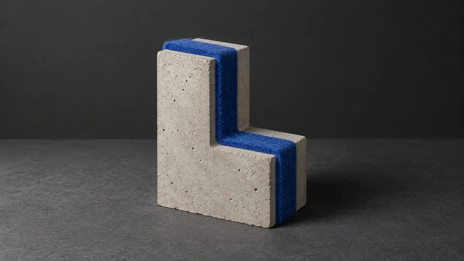
The useful investment is a repeatable junction whose consequences are understood before it is copied through the building. Spend modelling and inspection effort where they can change a decision. Local engineering review, governing project requirements, contracts, manufacturer instructions and actual site conditions control the final design. The cover’s felt strip is an editorial continuity metaphor, not an approved construction detail.
Sources & further reading
These primary sources support the claims and implementation frameworks used in this field note.
- 1. ZEB Technologies: Building Envelope & Architectural Considerations — thermal insulation
US Department of Energy
- 2. ISO 10211:2017 — Thermal bridges: heat flows and surface temperatures (public abstract)
International Organization for Standardization
- 3. THERM Software Downloads — components and modelling inputs
Lawrence Berkeley National Laboratory
- 4. ASTM C1363-24 — Hot-box testing of building assemblies (public scope and significance)
ASTM International
- 5. ISO 6781-1:2023 — Infrared methods for building irregularities (public abstract)
International Organization for Standardization
Sources checked on 18 September 2026. Numbered paragraphs summarize international references; the remaining text is OlbrichCo’s proposed review and implementation approach, not project results or standard clauses. ISO and ASTM citations use their public abstracts, scope and significance, not the full standards. Berkeley Lab documentation describes modelling tools; it does not approve a particular design or software version for the project. These sources are not Iranian law. Applicable requirements, contracts, manufacturer instructions, competent local engineering review and site conditions govern. No universal insulation thickness, surface-temperature limit, construction detail or numerical saving is prescribed.