Before Buying a Pump Drive, Prove the Operating Range
A variable-speed drive is only part of a pump retrofit. Establish the real duty profile, protect equipment and end-user service, and accept measured performance before repeating the investment across a building portfolio in Iran.
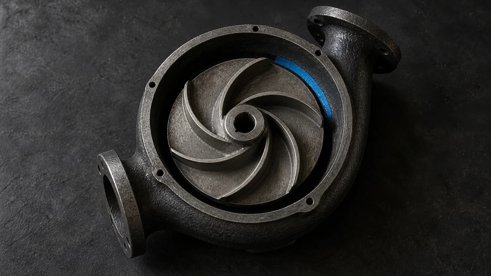
Buy a service outcome, not a frequency setting
Approve a pump retrofit against an operating envelope before approving the drive purchase. That envelope should connect building demand, required flow and pressure, permitted pump speeds, equipment limits and the fallback arrangement. OlbrichCo’s recommendation is to make it the shared brief for the owner, mechanical designer, controls contractor and operator. A cheaper drive or a lower displayed speed is not the acceptance outcome; maintaining the agreed service with demonstrably lower energy use is.
The US Department of Energy’s pump sourcebook advocates a system-level assessment: establish current conditions, collect operating data and duty cycles, identify demand requirements, and compare improvement options against system performance. [1]
Apply this note to centrifugal pumps in closed, recirculating building heating and cooling systems. Do not copy its workflow directly to fire or other life-safety pumps, sewage, positive-displacement pumps or specialist process systems. Water-transfer and booster duties need their own hydraulic review, particularly where static lift or a fixed delivery pressure matters. Existing equipment documentation and the responsible engineer must define the actual scope.
For a retrofit in Iran, commission a baseline during representative occupied operation, not only a quiet plant-room visit. Record synchronized flow, pump differential pressure, electrical input, speed, valve states and the associated heating or cooling demand. Include low, normal and high demand, with hours in each condition. State instrument accuracy and missing periods. If seasonal peak operation cannot yet be observed, identify the assumption and defer that part of acceptance explicitly.
Use the system curve before the cube law
Hydraulic Institute explains operating points through pump and system curves, including static and friction head. Changing pump speed changes the pump curve; active control valves require their control action to be considered as well. [3]
DOE’s speed-control tip sheet presents the cubic speed–power relationship for centrifugal pumping with little or no static head, and warns that systems with static head need system-curve analysis to determine new duty points. [2]
Ask the mechanical designer to plot the measured duties and proposed speed range on the actual pump curves, with relevant valve and parallel-pump configurations. Reject an annual savings estimate obtained simply by cubing a proposed speed reduction. For the investment comparison, require electrical input at each credible duty, expected hours there, and the assumptions behind both. Treat the estimate as a forecast to test, not as a result already achieved.
Compare variable speed with correcting an inappropriate control sequence, changing pump staging, manufacturer-approved impeller trimming, or selecting a better-sized pump. For a largely steady duty, ask what variation the drive is actually intended to serve. Compare installed cost, planned outages, commissioning effort, service access and replacement support. Leave the existing arrangement as a documented option when the evidence does not justify a change; a retrofit programme need not prescribe the same hardware everywhere.
Agree the operating limits before the minimum speed
Hydraulic Institute distinguishes the preferred operating region around best efficiency from the wider allowable region. Acceptable limits depend on the pump and constraints such as vibration, temperature, hydraulic loads and suction conditions; the manufacturer defines the applicable range. [4]
Request written confirmation of the proposed pump’s permitted range at the intended speeds, not a single catalogue duty point. Have the designer reconcile it with minimum flows through chillers, boilers and other connected equipment, suction conditions and the relevant cavitation margin. Do not choose a universal minimum frequency. Put unresolved limits on the procurement hold list; a drive should not be ordered on the assumption that controls will solve them later.
Define which circuit must receive the required service and how the controls will know it is being served. Let the designer select pressure-sensor location and any setpoint-reset logic from the actual distribution layout. Document valve authority, pump staging and minimum-flow arrangements together. Any bypass must be an engineered provision, not an improvised way to silence an alarm. Require review of how the sequence behaves when a terminal circuit opens or closes.
Give operators a readable sequence with permitted adjustments, alarm responses and restart conditions. Before testing, approve how sensor loss, a stopped duty pump and a return of power will be handled. Simulate faults only through an authorized method with service protection and a recovery plan; never defeat protective devices to demonstrate a control feature. Define who can change settings and retain an identifiable approved configuration after each change.
Check the motor, installation and support chain
ABB’s bearing-current guide explains that high-frequency currents in AC-drive systems can damage motor bearings. It describes cabling, earthing and other mitigation measures whose selection depends on the installation and equipment instructions. [5]
Assign the electrical designer a documented compatibility review covering the actual motor, drive, cable route and length, earthing, required filters, protection and power-quality implications. Confirm cooling and any temperature or altitude derating against current product manuals. If generator operation is part of the building’s service plan, include that supply in the review. Require qualified personnel and an approved isolation procedure for installation and measurements; this note is not a wiring instruction.
For procurement in Iran, verify the exact deliverable models, local commissioning capability, spare-part route and the ability to replace or restore the drive without an unavailable remote service. Keep original manuals, controlled Persian operating instructions and an offline parameter backup with the operator. If a substitute motor or drive is offered, reopen the compatibility review. Do not treat a matching power rating as sufficient approval for substitution.
Separate equipment price from enclosure work, sensors, cable changes, testing, training and support in the tender comparison. Ask who owns the integrated result when the pump supplier, electrician and controls contractor are different firms. Name one party to coordinate the interfaces, with the owner’s engineer retaining acceptance authority. Use project quotations and the owner’s actual energy-billing basis for the business case; do not insert a generic Iranian tariff or a promised payback period.
Accept the hydraulic service and the electrical result together
CIBSE’s 2025 Code W overview covers pre-functional and functional testing of closed hydronic systems. Its published contents include flow regulation, performance testing, handover, fine-tuning and seasonal testing during use. [6]
Turn the approved envelope into a witnessed test schedule. For each agreed demand condition, record required and achieved flow or differential pressure at the defined service boundary, pump speed, electrical input and any unstable control behaviour. Agree tolerances and stabilization periods before testing, using the design and equipment requirements. Include approved changeover and restart tests. A low electrical reading with an under-served circuit is a failed service test, not an energy success.
Measure before and after at a consistent electrical boundary that includes the drive in the retrofit case. Preserve raw readings, timestamps, instrument records and operating context. Compare equivalent service and demand conditions; where they differ, document the agreed adjustment method and its uncertainty. Do not present a short low-load test as annual savings. Make seasonal work outstanding until the required conditions occur, with a named owner and a return date.
At handover, give the operator the accepted curves and limits, test results, final parameter file, sensor locations, alarm and recovery instructions, and maintenance contacts. Demonstrate the approved local recovery procedure. Close supplier exceptions in writing, and distinguish accepted performance from deferred tests. Retain the original baseline so a later controls change or equipment replacement can be assessed against the same service obligation.
Scale the evidence, not the sales claim
Pilot a clearly bounded, maintainable circuit before buying drives for an entire portfolio. Track energy over comparable operating periods, hours inside the accepted service range, low-flow or pressure excursions, unexpected trips, control oscillation, overrides and recovery time. Show missing data and demand conditions alongside results. Use these measures to decide whether to repeat the package, revise its control sequence or reject it for a different duty.
Review the record after the first relevant heating or cooling season and after changes to occupancy, terminal units or pump staging. Revisit the decision if the operating envelope changes or the replacement support assumed at purchase is no longer available. The useful deliverable is a maintainable pump system with a traceable performance basis, not merely a commissioned drive.
Applicable Iranian requirements, project specifications, contracts, current manufacturer instructions, actual site conditions and qualified local engineering review determine the final design and authority to accept it. This is a decision framework, not a claim of Iranian code compliance or a numerical return on investment. Approve variable speed when the verified duty and support arrangements justify it—and retain an explicit alternative when they do not.
Sources & further reading
These primary sources support the claims and implementation frameworks used in this field note.
- 1. Improving Pumping System Performance: A Sourcebook for Industry, Second Edition (2006)
U.S. Department of Energy
- 2. Adjustable Speed Pumping Applications — Pumping Systems Tip Sheet #11 (2007)
U.S. Department of Energy
- 3. Pump System Operating Point — HI Data Tool
Hydraulic Institute
- 4. Pump FAQs — Best Efficiency Point and Preferred/Allowable Operating Regions
Hydraulic Institute
- 5. Technical Guide No. 5 — Bearing Currents in Modern AC Drive Systems, Revision C (2011)
ABB
- 6. Commissioning Code W: Water Distribution Systems (2025) — Public Overview and Contents
CIBSE
Sources checked on 10 September 2026. Cited paragraphs summarize public guidance; uncited recommendations are OlbrichCo analysis and implementation advice. The CIBSE reference is its public 2025 overview and contents, not the full code. Older DOE and ABB publications support established principles, not current product performance. These references are not Iranian law. Governing requirements, contracts, current equipment documentation and qualified local engineering review control; no universal speed setting or savings figure is proposed. The cover is an editorial metaphor, not an assembly drawing.