Airtightness Is a Building Result: Test the Whole Envelope
A staged acceptance plan for Iranian projects that turns a drawn air barrier into a defined, inspectable, pressure-tested boundary without confusing tightness with ventilation.
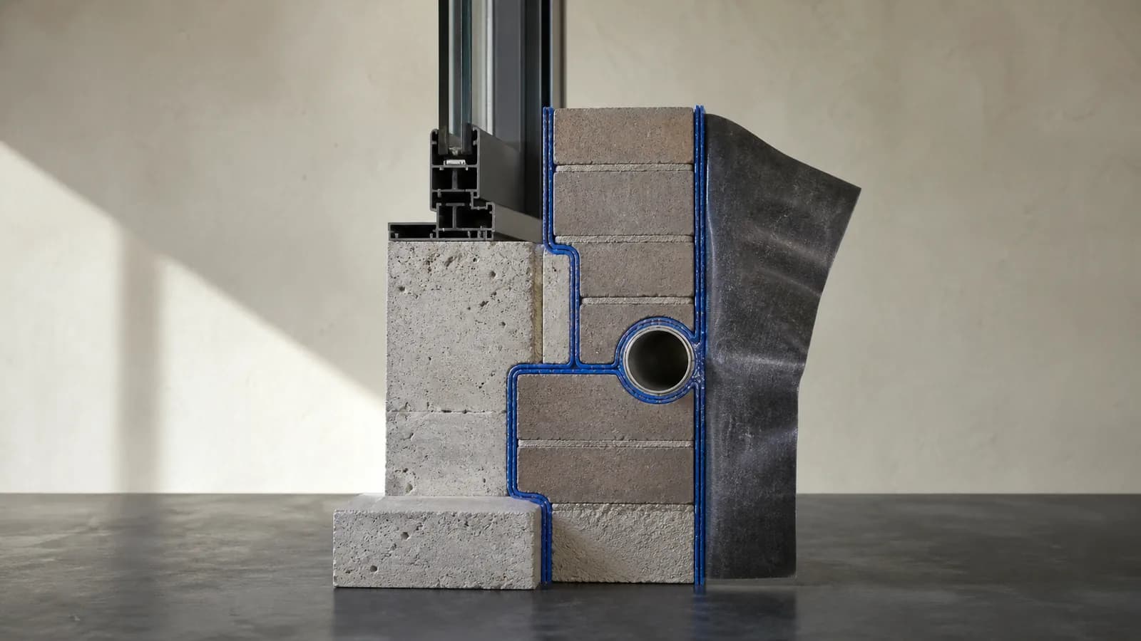
The product is continuity, not membrane area
A material certificate answers only one layer of the question. ASTM E2357-25 measures representative air-barrier assemblies and warns that laboratory results may not represent field-installed performance. ASTM E3158-24 addresses the constructed envelope, where sequencing, workmanship, and transitions become part of the result; the GSA P100 likewise requires a continuous boundary across all six sides of buildings within its scope. [4][2][6]
OlbrichCo analysis: treat airtightness as an interface-control problem. A large area of competent concrete, plaster, sheet membrane, or glazing can still be defeated by one unowned joint at the slab edge, roof upstand, entrance, shaft, or service penetration. The procurement package should therefore buy continuity and a testable outcome—not square metres of a named product.
Write the pressure boundary before the leakage target
ISO 9972:2015, reconfirmed as current in 2026, measures buildings or parts of buildings by mechanical pressurization or depressurization over a range of indoor–outdoor pressure differences. ASTM E3158-24 separately defines envelope and operational preparation conditions and states that the method measures compliance with a target established elsewhere; it does not set that target for the project. [1][2]
Before tender, issue a one-page test-basis schedule and mark the boundary continuously on plans and sections. State which doors, dampers, drains, vents, shafts, temporary openings, and HVAC paths are sealed, closed, open, or left in normal operation; define the reporting denominator, reference pressure, test direction, weather limits, instrument requirements, retest rules, and who may authorize preparation. Without that schedule, two technically competent tests can produce numbers that are not contractually comparable.
- One colour and line type for the pressure boundary on every plan and section.
- One test standard, preparation condition, metric, denominator, reference pressure, and target.
- A separate register of intentional openings and their test-state treatment.
- Defined readiness, calibration, weather, safety, witness, report, and invalid-test rules.
- No imported universal limit: contract, code, energy model, use, climate, and engineering review control.
Give every boundary handoff an owner and buildable detail
The 2024 GSA P100 asks construction documents to demonstrate constructability and clearly illustrate continuity of the air barrier. UFGS 07 27 10 similarly calls for plan and section diagrams, compatible adjoining materials, and a traceable plane through windows, doors, dampers, ducts, roofs, floors, and wall transitions for projects using that specification. [6][7]
On Iranian concrete-frame buildings, the difficult work will often be where trades meet: concrete to infill, infill to window or stone support, wall to roof, façade to entrance, and pipe or duct to wall. Name the designer, supplier, installer, inspector, and repair owner for each junction. Require substrate tolerances, backing, movement capacity, primer, lap, fastener, fire-stopping, waterproofing, and replacement compatibility to be resolved together; airtightness must not compromise drainage, drying, structure, fire resistance, or maintainability.
- Structural movement and construction tolerances at slab edges and façade anchors.
- Concrete or masonry substrate preparation before the control layer is concealed.
- Window, door, curtain-wall, roof, and below-grade transitions as installed—not in isolation.
- Pipes, conduits, cable trays, ducts, dampers, and future service capacity.
- Interfaces with water, vapour, thermal, acoustic, fire, and access-control layers.
Build the hardest junction first and keep it visible
ASTM E2357-25 can be applied to site mock-ups, while UFGS 07 27 10 describes a preconstruction mock-up that includes floor-to-wall, wall-to-window, wall-to-roof, material transitions, and representative penetrations. The same UFGS calls for installation records and inspections of continuity, substrate condition, adhesion, laps, thickness, compatibility, and transitions on work governed by it. [4][7]
Choose the least forgiving repeated bay, not the cleanest elevation, for the project mock-up. Test adhesion and local leakage while both sides remain accessible, agree the repair method, photograph the accepted sequence, and turn it into a field standard. Then place hold points before insulation, cladding, ceilings, riser closure, and finishes erase the repair path. A final whole-building test is valuable, but it is an expensive time to discover a buried discontinuity.
- Approve materials only after compatibility and actual-substrate trials.
- Record location, batch, installer, substrate, weather, inspection, defect, repair, and closure evidence.
- Use first-installation and change-trigger inspections for every critical junction family.
- Do not cover a failed or uninspected boundary; assign a named release authority.
- Retest repairs with the same boundary, setup, instrument logic, and acceptance basis.
Use zonal testing to move evidence ahead of handover
ASTM E3474-25 introduced a quantitative method for the exterior envelope of an individual zone within a multizone building. It is intended for situations where some areas are ready while others remain inaccessible, in use, or incomplete, but it requires controlled pressure relationships with surrounding zones and careful treatment of flanking airflow. ASTM E3158-24 remains the reference for large or multizone whole-building testing. [3][2]
That distinction is useful for phased residential towers, hospitals, hotels, industrial buildings, and partial renovations—but a random room test is not automatically a valid zonal envelope test. Divide the project by real pressure boundaries and construction sequence, make adjacent-zone balancing feasible, choose representative and high-risk zones, and preserve a final test strategy for the completed building or agreed test envelope. Zonal passes reduce uncertainty; they do not silently replace the contracted final acceptance.
- Map testable zones during design, before temporary partitions and access decisions are fixed.
- Select high-risk interfaces as well as repeated typical zones.
- Monitor pressure in adjacent spaces and document all temporary sealing and flanking paths.
- Link each zone result to drawing revision, readiness record, defects, repairs, and final status.
Separate measurement, diagnosis, and repair
ASTM E3158-24 explicitly says that a compliant aggregate leakage rate does not prove every problematic leak is sealed and that the quantitative test does not locate leaks. ASTM E1186-22 covers qualitative location methods such as infrared scanning, smoke or fog, anemometry, sound, bubbles, tracer gas, and local chambers; the suitable technique depends on access, pressure direction, construction, and environmental conditions. [2][5]
Write three records: the calibrated measurement report, a location-based defect map, and the repair-and-retest register. Prioritize leaks by consequence, not only apparent size: an intake near pollutants, a wet-climate outward path, a smoke-control boundary, or a concealed joint may deserve action even when the aggregate number passes. Conversely, sealing an intended drain, combustion-air path, relief opening, or required ventilation route can create a new hazard.
Testing itself needs a method statement. Fan-induced pressures can move doors, disturb temporary closures, affect lifts or dampers, spread dust or fumes, and interact with active systems. Establish exclusion zones, communications, door restraints, emergency release, sensitive-space protection, weather criteria, and MEP/fire/life-safety authorization before energizing the fans.
Pilot one boundary and measure the quality of closure
Start with one consequential, repeatable zone whose structure, infill, opening, façade, service penetration, and finish sequence represent the project. Freeze its test basis; complete design review and mock-up; inspect before concealment; run an early quantitative test and targeted diagnosis; close defects; then retest. Use the result to decide whether details, responsibilities, training, sequencing, or the project-wide sampling plan must change.
Measure control as well as airflow: percentage of boundary details with a named owner; first-pass inspection and test rate; defects by junction family; median days from detection to verified closure; uninspected work concealed; test invalidations; final leakage result under the agreed setup; and unresolved high-consequence leaks at handover. Keep baseline and final reports, preparation schedules, calibration evidence, defect maps, photographs, repairs, and future penetration rules in the facility record.
Airtightness is not a substitute for designed outdoor air, pressure relationships, smoke control, moisture analysis, or safe combustion and exhaust. The final target and remedy are project decisions governed by applicable Iranian requirements, the signed contract, the energy and ventilation strategy, actual site and climate conditions, and responsible professional review. This plan offers an evidence chain, not a universal performance limit or a claim of guaranteed savings.
- Zero boundary segments without a designer, installer, inspector, and closure owner.
- Zero critical interfaces concealed without the required inspection release.
- Every quantitative result tied to one reproducible boundary and preparation schedule.
- Every high-consequence leak mapped, dispositioned, repaired where required, and verified.
- A facility rule for reviewing and resealing every future penetration through the boundary.
Sources & further reading
These primary sources support the claims and implementation frameworks used in this field note.
- 1. ISO 9972:2015 — Thermal performance of buildings: Determination of air permeability by fan pressurization
International Organization for Standardization
- 2. ASTM E3158-24 — Measuring the Air Leakage Rate of a Large or Multizone Building
ASTM International
- 3. ASTM E3474-25 — Measuring Air Leakage of an Individual Test Zone within a Multizone Building
ASTM International
- 4. ASTM E2357-25 — Determining Air Leakage Rate of Air Barrier Assemblies
ASTM International
- 5. ASTM E1186-22 — Air Leakage Site Detection in Building Envelopes and Air Barrier Systems
ASTM International
- 6. P100 2024 — Facilities Standards for the Public Buildings Service
U.S. General Services Administration
- 7. UFGS 07 27 10 — Building Air Barrier System
U.S. Department of Defense — Whole Building Design Guide
Sources were checked on 28 August 2026. The foreign standards and public specifications describe test methods and requirements in their own jurisdictions; they do not create Iranian legal obligations. The test boundary, leakage target, building preparation, safety, ventilation, moisture control, acceptance, and final handover must follow governing requirements, the signed contract, actual climate and use, manufacturer instructions, and responsible architectural, enclosure, MEP, fire, and safety review.